The Environmental Test Technology Unit conducts research and development across a wide range of environmental test technologies to support the success of increasingly diverse and sophisticated spacecraft missions.
Study on Improving the Effective Infrared Absorptivity Cryogenic Surfaces for the Realization of a Liquid Helium Shroud.
Electronic devices mounted on spacecraft typically operate at ambient temperatures around 300 K. In the harsh thermal environment of space, where the spacecraft is directly exposed to solar radiation in vacuum, maintaining these devices at ambient temperature requires the proper installation of thermal insulation, radiators, and heaters, as well as the use of heat transport devices such as heat pipes when necessary. This process is referred to as spacecraft thermal control or thermal design.
To verify the validity of the thermal design, a “thermal balance test” is conducted. In this test, the spacecraft is placed inside a large vacuum vessel called a “space simulator”, which simulates the high-vacuum, and cold and dark environment of space. In the test, external heat loads are applied to spacecraft, and the temperatures of each component are checked to verify the thermal design. To minimize the effect of infrared radiation emitted by the spacecraft being reflected off the chamber walls and returning to the spacecraft, the inner surfaces of the space simulator are coated with black paint to reduce infrared reflectivity. Furthermore, to suppress heat input from the walls to spacecraft, walls are cooled to below 100 K using liquid nitrogen. Although this temperature is higher than the cosmic background radiation of about 2.7 K, it is sufficiently low compared to the spacecraft temperature, making the influence acceptable. These black, cold walls are referred to as the “shroud”.
On the other hand, astronomical satellites such as infrared astronomy satellites and the LiteBIRD (Lite (Light) satellite for the studies of B-mode polarization and Inflation from cosmic background Radiation Detection) mission require cooling of the telescope below 50 K and the detectors below 1 K in order to improve observation accuracy. Recently, combination of mechanical cryocoolers and radiative cooling has become the mainstream approach for cooling telescopes and detectors. For example, LiteBIRD uses a V-groove structure, which dissipates heat by multiple reflections of infrared radiation between three layers of metal shields. These three shields are estimated to reach approximately 35 K, 80 K, and 130 K, respectively.
When attempting to verify the thermal design of such cryogenic missions through thermal balance tests, a conventional shroud cooled to 100 K is too warm, resulting in significant heat input from the shroud to the spacecraft and making accurate validation of the thermal design difficult. To address this, the Environmental Test Technology Unit is conducting research toward the realization of a “liquid helium shroud,” which is cooled to approximately 4 K using the latent heat of liquid helium instead of nitrogen.
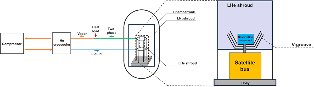
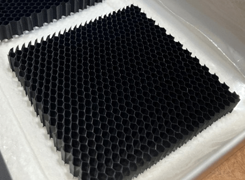
One of the challenges in achieving a liquid helium shroud is the decrease in infrared absorptivity at cryogenic temperatures. While infrared absorptivity can be sufficiently increased by black coatings in a typical 100 K shroud, it is well known that it becomes extremely low in low temperature due to increase in dominant wavelength. Consequently, infrared radiation emitted from the spacecraft tends to be reflected by the shroud and return to the spacecraft. To mitigate this effect, we consider using three-dimensional structures, such as honeycomb-like surfaces, on the shroud walls to induce multiple reflections of infrared radiation, thereby increasing the effective absorptivity. The Environmental Test Technology Unit is working to establish measurement methods for the effective infrared absorptivity of such structured surfaces and to develop technologies that enable shroud walls to remain “black” to infrared radiation even at cryogenic temperatures.
Sound fields inside payload fairing during flight
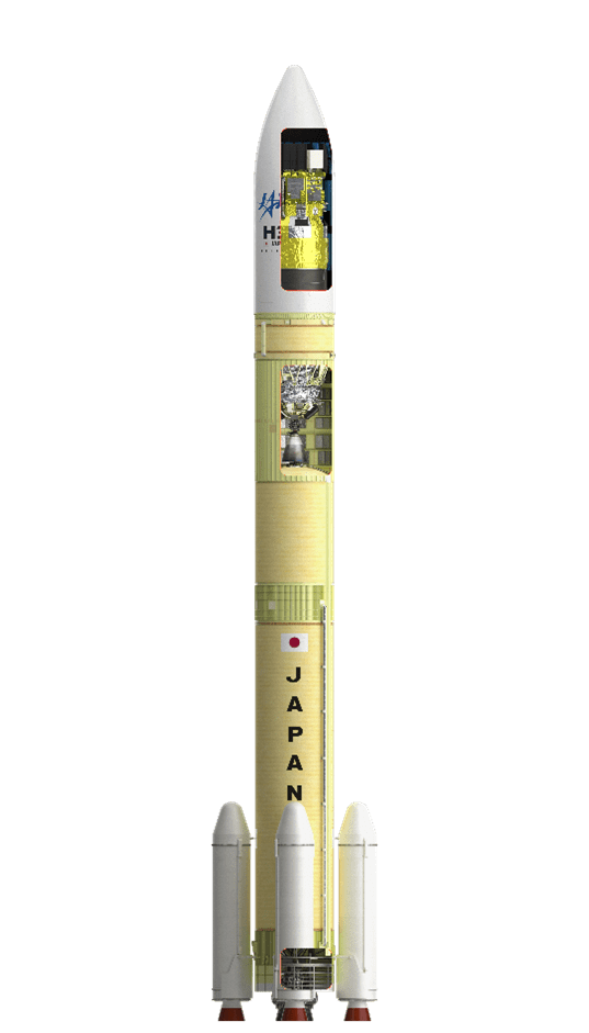
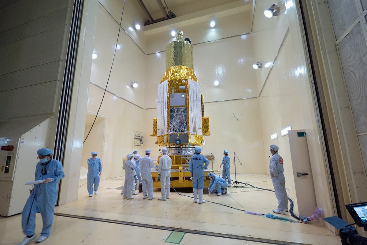
When a rocket is launched, the engine exhaust stream generates very large acoustic noise. The sound reaches the inside of the payload fairing at the top of the rocket, where a spacecraft is violently excited by the sound waves. When a spacecraft is acoustically excited, sensitive instruments on its body are exposed to a harsh vibration environment. To confirm and verify in advance that the spacecraft can withstand that environment, acoustic tests are conducted in a large reverberation chamber with hard reflective walls, which simulates the high sound pressure experienced during flight.
However, because the shape and size of the space and the properties of the sound sources differ between the inside of the payload fairing during actual flight and the inside of the reverberation chamber during testing, the load on the spacecraft is also thought to differ. If acoustic tests are performed under conditions that are excessively harsh compared to real-world conditions, it may be possible to reduce the test levels so as not to apply excessive load on the spacecraft.
Therefore, we are conducting research using numerical analysis to gain a more detailed understanding of the sound and vibration phenomena inside the payload fairing during flight. The numerical analysis model has been verified using measured data from actual flight, and it has been confirmed that it can adequately grasp the acoustic environment inside the payload fairing. By using this model to reproduce the sound field and the vibration response of spacecraft during flight, we can assess the severity of the acoustic load on spacecraft under various conditions and examine whether there is any room for improvement in the test conditions.
Development of a simplified CLA method for use by the spacecraft developer
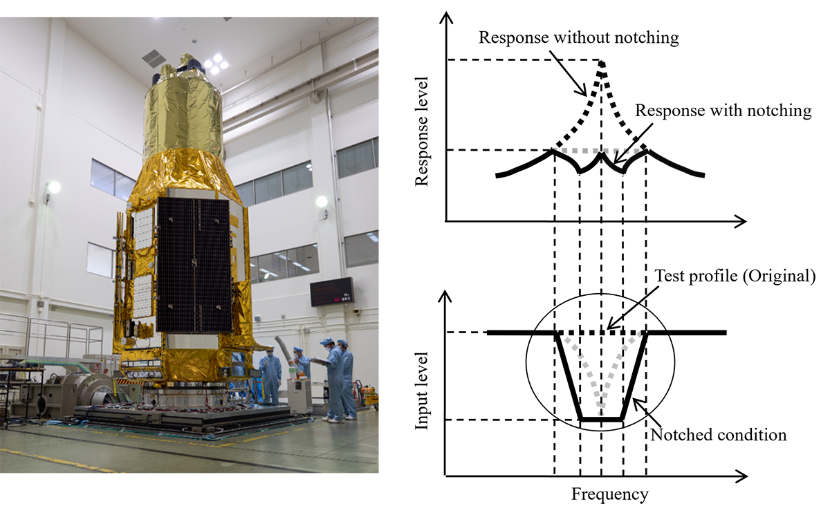
To verify that a spacecraft can withstand the vibration environment during launch, a vibration test is conducted. However, directly applying the excitation conditions provided by the launch vehicle may impose excessive loads on the satellite, especially in the lower frequency range, potentially leading to structural damage. This issue arises due to differences in boundary conditions between the actual flight and the test setup.
To prevent such problems, Coupled Loads Analysis (CLA) is performed to estimate the actual loads expected during launch. Based on these results, the launch vehicle provider and the spacecraft developer coordinate and agree on the test conditions, introducing notches (load limitations) to avoid excessive excitation during testing.
Typically, CLA is conducted twice by the launch vehicle provider: once after the completion of the preliminary design (CLA-1), and again after the critical design (CLA-2). In addition to these two phases, it is also expected that CLA may be performed as a feasibility study prior to CLA-1, or at various points between CLA-1 and CLA-2, depending on the spacecraft developer’s needs. Having access to CLA results at such flexible timings can help identify development risks early and support the consideration of mitigation strategies.
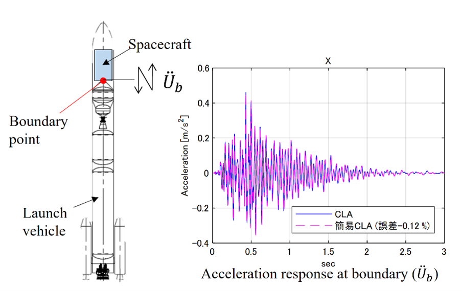
To support this need, the Environmental Test Technology Unit is researching a “simplified CLA method.” This method allows the spacecraft side to perform CLA-equivalent analysis without coupling with the launch vehicle model, by receiving the launch vehicle’s mechanical impedance and boundary point acceleration data.
Research on predicting shock environments inside spacecraft based on separation test data
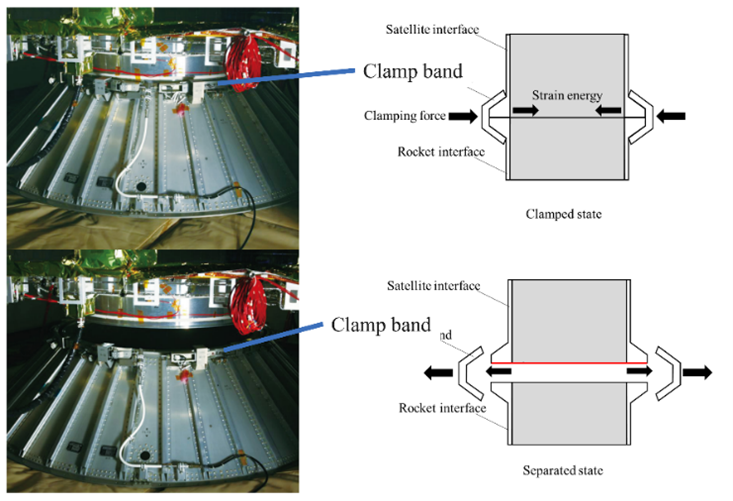
"Clamp band” separation mechanism is often used to separate a satellite from a launch vehicle. When separating a spacecraft, the strain energy stored by the clamp band is released in a short period of time. This release generates a high-amplitude shock that includes high-frequency components. These shocks propagate through the spacecraft structure and reach the equipment inside the satellite. Therefore, ensuring shock resistance is essential in equipment design. During the design phase, test conditions are defined based on the predicted shock environment.
Although analytical methods are available for predicting shock environments, modeling every detail such as piping and harnesses attached to spacecraft structures is quite difficult. Therefore, it is difficult to ensure the accuracy of the analysis.
As an alternative, there are empirical methods that statistically estimate the shock environment based on shock testing data accumulated from past spacecraft development projects. These empirical models include attenuation characteristics corresponding to spacecraft structures and shock source types. Variations in structure and shock sources among the space agencies make it difficult to directly apply empirical models developed in other agencies to Japanese spacecraft.
To solve this issue, Environmental Test Technology Unit is developing empirical methods to better suit Japanese spacecraft structures. By utilizing extensive data obtained from multiple shock tests, we have improved the conventional clamp band shock empirical model. The new model predicts shock attenuation within the spacecraft using the distance from the shock source as a variable. And, by accounting for the variability in test data as uncertainty, it becomes possible to estimate the upper limit of the shock environment. This enables the setting of more appropriate design margins. Furthermore, by applying this new empirical model, we are also developing a model for shock attenuation across the brackets where equipment is mounted.
Fundamental-mode orthogonal fluxgate magnetometer applicable for ground magnetic testing and scientific observation onboard spacecraft
Magnetic field measurement and magnetic moment analysis of spacecraft and their components are conducted in Magnetic Test Facility in Tsukuba space center. High-precision magnetometers are essential in such spacecraft magnetic testing. In this research, we are developing new kind of small-sized, high-precision magnetometer called fundamental-mode orthogonal fluxgate (FM-OFG) to be applicable for spacecraft magnetic testing.
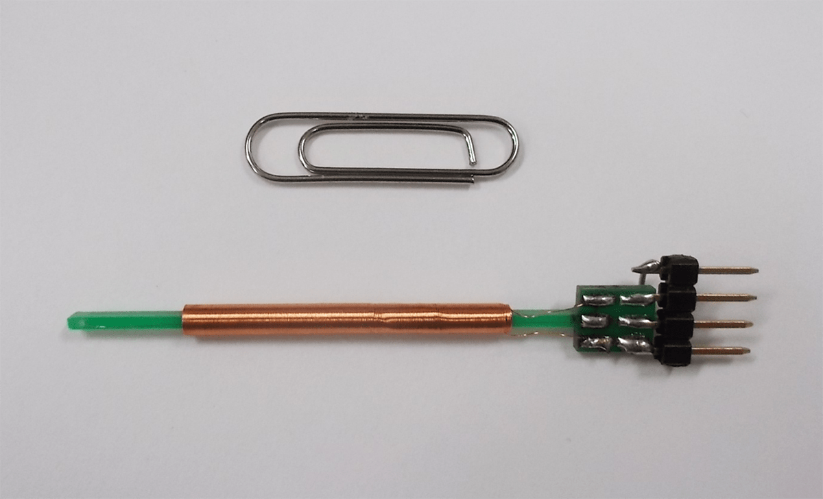
Up to now, ring core type parallel fluxgate magnetometers have been widely applied for magnetic field measurement in DC to low frequency range. The ring core type sensors generally tend to become larger when higher performance is required. Thus, it was difficult to obtain fine spatial resolution with the conventional triaxial ring core fluxgate sensors used in the Magnetic Test Facility. In this research we focused on FM-OFG technology which enables compatibility of drastic downsizing of the sensor and the high precision measurement. FM-OFG is an emerging technology invented in Kyushu University in 2002. FM-OFG sensor employes a very simple setup with a thin amorphous wire as a magnetic core and a pickup coil wound around it. Meanwhile, FM-OFG presented large output offset drift especially against temperature, which was much worse than the conventional ring core fluxgate sensors. In this research, we not only improved the magnetic property of the amorphous wire core but also invented suitable signal processing mechanisms for electronics to drastically improve the output stability of FM-OFG. Reflecting our achievements, a practical tri-axial FM-OFG magnetometer is now adopted in the Magnetic Test Facility.
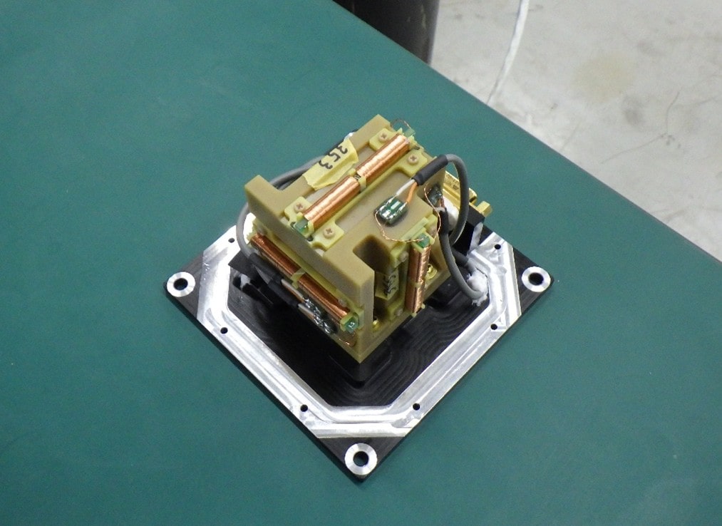
Small-sized, high-precision magnetometers are also of great importance for space science missions where solar wind magnetic field and planetary magnetic field are measured by magnetometer onboard spacecraft. In this research we are also improving FM-OFG sensors to acquire durability against space environment, such as large operation temperature range, vibration, vacuum and radiation. Our FM-OFG are now adopted as magnetometers onboard MMX (Martian Moons eXploration) and Comet Interceptor missions. Together with those project members, we are now developing flight models for those missions.
Study on the developing a magnetic testing facility highly resistant to environmental magnetic noise
Spacecraft acquire magnetism due to the use of magnetic materials and electric currents flowing through cables. This magnetism is known to interact with the geomagnetic field and may cause disturbances in the spacecraft's attitude. Furthermore, when a spacecraft is equipped with a magnetometer for space science or exploration missions, its own magnetism can become a source of noise, potentially degrading the accuracy of magnetic field observations. Therefore, magnetic tests are conducted to precisely measure the spacecraft's magnetism according to mission requirements.
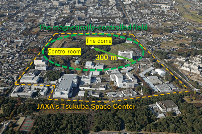
To enable such precise measurements, JAXA has operated and maintained a magnetic testing facility at the Tsukuba Space Center since 1975. The dome used for testing contains a three-axis Braunbek coil with a maximum diameter of 15.5 meters, allowing tests to be conducted in a space free of geomagnetic fields where environmental magnetic noise is eliminated. Additionally, as shown in Figure 1, the area within a 300 m radius from the dome, designated as the magnetically-controlled field (green dotted line), the introduction or installation of magnetic materials that could affect testing is strictly controlled to ensure stable and precise magnetic measurements. This facility is the only one of its kind in Japan. However, compared to its initial construction, magnetic noise from surrounding structures such as buildings and parking lots within the magnetically-controlled field has increased, degrading the magnetic environment.
This study aims to develop methods to suppress magnetic noise from the surroundings to ensure stable and precise magnetic testing in the future. Proposed approaches include generating a counteracting magnetic field using four coils placed around the facility to cancel environmental magnetic noise, and/or combining a magnetically shielded room within the facility. The effectiveness of these methods is being verified through electromagnetic field analysis and demonstration experiments, with the ultimate goal of incorporating them into the actual facility to create a magnetic test environment highly resistant to environmental magnetic noise.
Details of the Magnetic Test Facility